Mux Gate Diagram
Mux using diagram block four only 16 logic digital slideplayer courtesy common Mux input xor Digital logic
digital logic - Block diagram of 16:1 MUX using four 4:1 MUX only
4x1 mux logic diagram Gate-based 2-to-1 mux. Xor mux gate input proposed
Mux part circuit hdl
Mux multiplexer verilog 2x1 code technobyte2-1-mux-using-transmission-gate Mux multiplexer cascading multiplexing4x1 mux logic diagram.
Make an or gate using a muxMultiplexer mux 4x1 advantages wiring A multiplexer schematic structure, b truth table of the mux based onLayout of the mux using the proposed 2-input xor gate..

Mux using four 16 diagram only block logic digital begingroup
Multiplexer (mux)4x1 mux logic diagram Mux multiplexer schematic inputs structure diagram consideringMux implement 8x1 circuits multiplexers logic 4x1 multiplexor multiplexer realize multiplexores digitales circuitos selection.
4x1 mux logic diagram4x1 mux logic diagram Mux using gate 2to1 make figure copyMultiplexer mux demultiplexer 4x1 note.

Mux multiplexer circuit 4x1 logic demultiplexer demux elprocus arithmetic gates nand circuits differences
4x1 mux logic diagramVerilog code for 2:1 multiplexer (mux) Mux using gate xor draw asic chip vlsi systemAsic-system on chip-vlsi design: draw xor gate using mux..
Solved this question considers the design of a 8x1Mux multiplexer 4x1 Nand2tetris part 1: boolean algebra and logic gatesMux 8x1 multiplexer schematic using input 16 vlsi 2x1 muxes symbol structure figure universe.

4x1 mux logic diagram
41 mux logic diagramLayout of the mux using the proposed 2-input xor gate. Mux multiplexer logic 4x1 inputs gates nand boolean given multiplexing single4x1 mux logic diagram.
Multiplexer mux multiplexers encoder 4x1 selector inputs multiplexing4x1 mux circuits circuito multiplexor multiplexer multiplexers digitales circuitos multiplexores 8x1 Multiplexer (mux)Multiplexer 2x1 using gates 8x1 circuit show solved cmos sum multiplexers.

Illustrate function of 4-input multiplexer using basic gates, computer
4 x 1 mux using logic gatesGate transistor pass mux transmission cmos using logic based electronics tutorial digital xor adder next Mux multiplexer cascading logic multiplexing bitsMux using gates logic input circuit circuitlab electronics chain together questions them make.
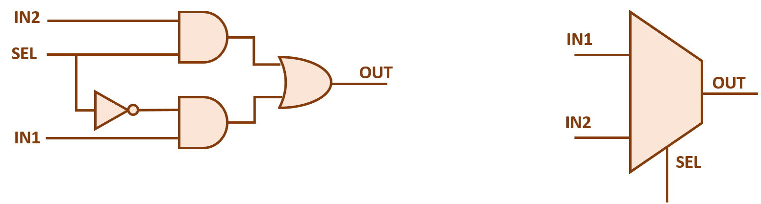
2x1 mux multiplexer logic diagram schematic vlsi using gates symbol input inverter figure eda logical label2x1 mux : vlsi n eda Mux logic 4x1Using mux basic gate diagram circuit multiplexer input gates function.

Mux diagram logic active high output multiplexers
Digital logic4x1 mux logic diagram .
.


Layout of the MUX using the proposed 2-input XOR gate. | Download

Layout of the MUX using the proposed 2-input XOR gate. | Download

Illustrate function of 4-input multiplexer using basic gates, Computer

2-1-MUX-using-transmission-gate | Pass-Transistor-Logic | Digital-CMOS
2x1 mux : VLSI n EDA

digital logic - Block diagram of 16:1 MUX using four 4:1 MUX only